Installing coreboot on a ThinkPad W541
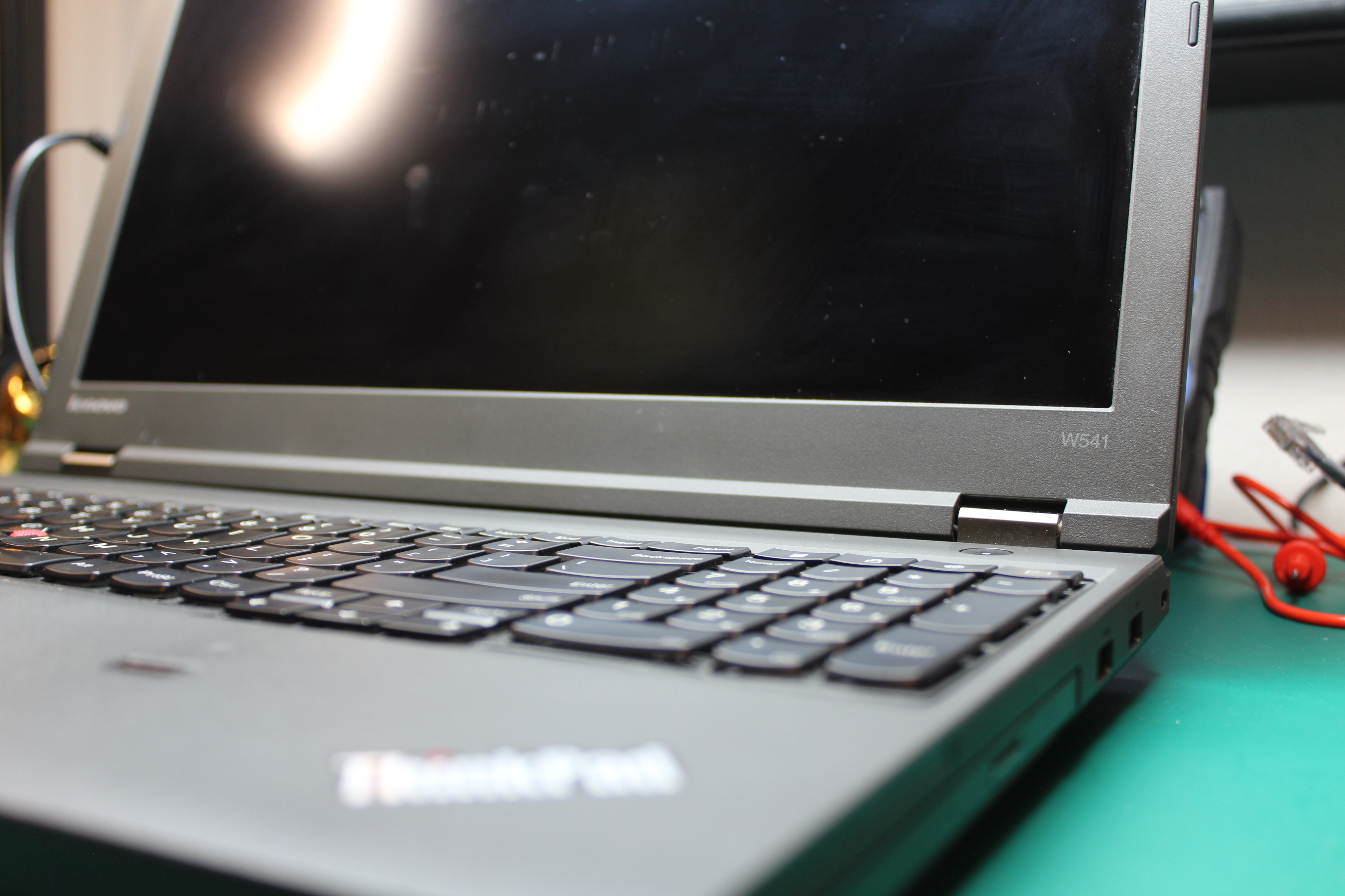
This guide will show you, step-by-step, how to install coreboot on a Lenovo ThinkPad W541. You’ll also learn how to get the Nvidia graphics working, even without having to extract the VGA Option ROMs. I’ll assume you have no prior experience installing coreboot before, and will attempt to create a single guide that can be used for additional machines as well.
The ThinkPad W541 is probably the most powerful ThinkPad that can be flashed with coreboot. It has 4 DIMM slots, a socketed CPU, and plenty of room for added internal storage, which makes it very easy to upgrade. The ThinkPad brand is also well known for providing a reliable and maintainable platform for this generation (with the T440p being the easiest to maintain ThinkPad I’ve come across).
Before we begin, let’s discuss some aspects of this particular machine and how it relates to coreboot. This guide uses a binary blob in the coreboot build, therefore it is not 100% libre. The binary blob is the mrc.bin file. Eventually, it’s highly likely that this machine, and the T440p, which makes use of the same mrc.bin file, will be 100% libre, since there is ongoing development of libre raminit which is used by the T440p and W541. For the mrc.bin blob, this guide will show you how to download a Haswell-based MRC from a Chromebook, that since is from a smaller and less-capable machine, we can reasonably assume it’s less “bad”.
Prerequisites
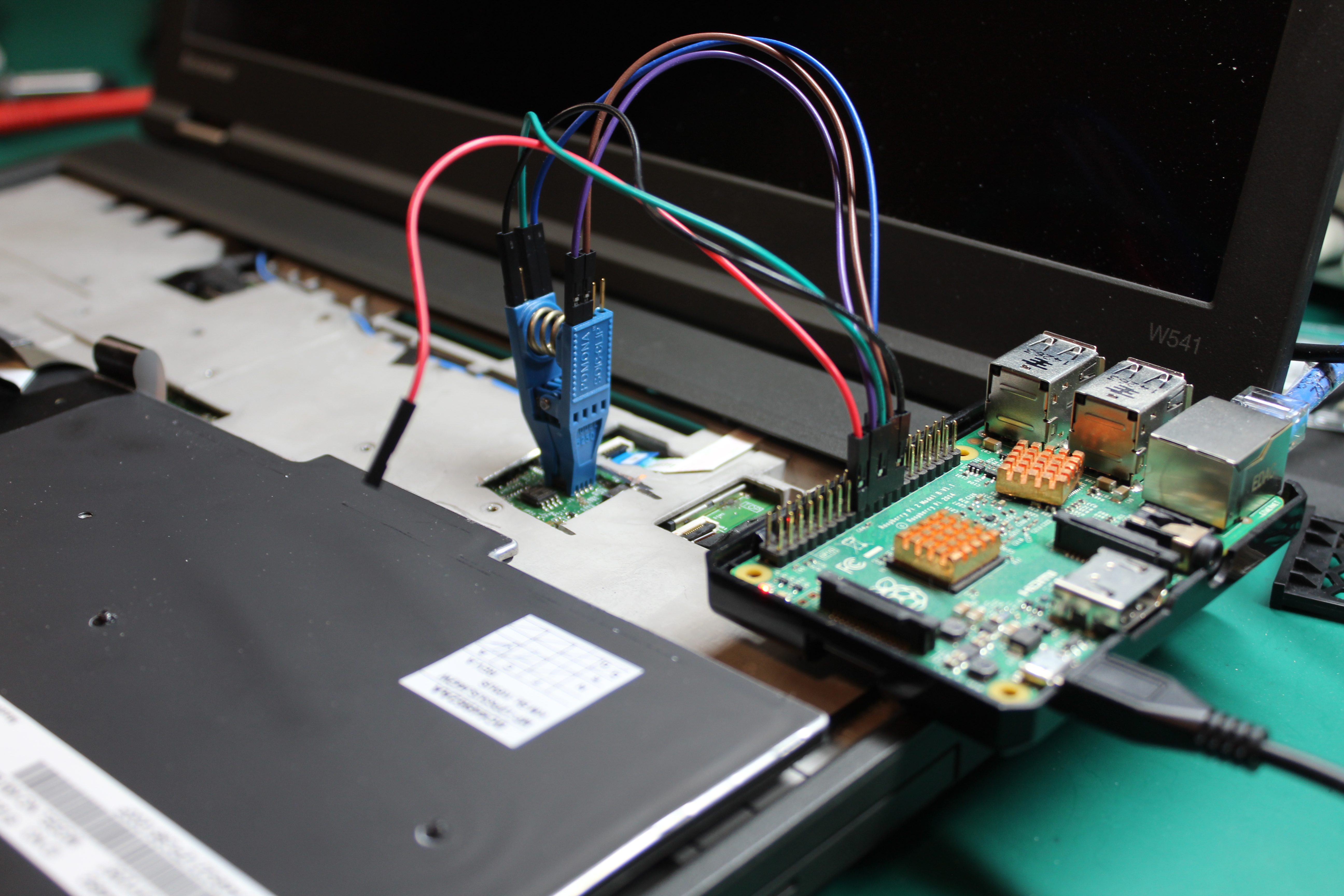
Since the W541 needs to be powered down and disassembled for external flashing, you can’t use it to flash itself the first time. The act of a machine flashing itself is called internal flashing, which will be possible after initially flashing coreboot with this guide. You’ll need a second computer that you have sudo capability on to use for running commands. You’ll also need an external flasher. An external flasher is just a machine or programmer that gives you the ability to interact directly with the BIOS chip using a program called flashrom. You can purchase a programmer that plugs into a USB port of the second machine, or you can use a Raspberry Pi. This guide will use a Raspberry Pi (specifically a 2b, but any 40-pin Pi will work exactly the same) as the external flasher, since that is what I have available.
You’ll also need a SOIC-8 clip and female-to-female jumper cables. The most commonly recommended clip is the Pomona SOIC Clip, 8 pin, and it’s available at plenty of online stores. For the jumper cables, you’ll only need 6 of them, and get them in 6-inch length, since the longer they are, the higher the chances are you could lose data when reading or writing to your BIOS chip. As far as purchases required for coreboot, this is basically it.
Before disassembling the W541 is also a good time to wire up the clip and the Pi.
Raspberry Pi’s 40-pin pinout (applies to any 40-pin Pi):
                          CS (24)
    2                     |             40
+-+-----------------------v---------------+-------------------+
| | x x x x x x x x x x x x x x x x x x x |                   |
| | x x x x x x x x x x x x x x x x x x x |                   |
| +-----------------^-^-^-^-^-------------+                   |
|   1               | | | | |           39                    |
|                   | | | | GND (25)                          |
|           (17) VCC) | | CLK (23)         (rest of the Pi)   |
|           (19) MOSI/   \MISO (21)                           |
The W541’s BIOS chip layout:
                   ______
           CS 1 --|*     |-- 8 VCC
         MISO 2 --| BIOS |-- 7 No Connection
No Connection 3 --|      |-- 6 CLK
          GND 4 --|______|-- 5 MOSI
The ***** represents the indented dot on the chip, not any painted dot.
Mapping those together, that’s:
Chip <-> Pi
   1 <-> 24
   2 <-> 21
   4 <-> 25
   5 <-> 19
   6 <-> 23
   8 <-> 17
As previously mentioned, you’ll need flashrom on the Pi, but you’ll also need the ability to ssh into the Pi, and be able to securely copy files to and from it with your secondary machine. Assuming you’re using the official Raspberry Pi OS, you can install flashrom by simply running:
sudo apt install flashrom
Then you’ll need to do is enable the ssh server, by making use of the raspi-config application:
sudo raspi-config
Follow these steps in raspi-config:
- Go to Interfacing Options
- Select SSH
- Choose Yes
- Select Ok
- Choose Finish
Then you can get your Pi’s IP address with the ip address command and ssh into it from your secondary machine. You might also want to change its hostname, I named mine “flasher” so that I don’t have to memorize its IP address. When you’re finished, shut down the Pi and disconnect its power.
You’ll also want to enable the SPI interface on the Raspberry Pi. From the raspi-config menu, perform the following steps:
- Go to Interfacing Options
- Select P4 SPI
- Choose “Yes” to enable the SPI interface
Finally, you’ll need another, more powerful machine to do the actual compiling of coreboot on. This is because the Raspberry Pi is so slow, it would take hours to complete (if it even does, I gave up waiting for it my first time). On this machine, you’ll need to install some “essential” programs:
sudo apt install build-essential libncurses-dev m4 bison flex zlib1g-dev gnat python3
And also it’s a good idea to alias python3 to python since coreboot will look for the latter:
sudo ln -s /usr/bin/python3 /usr/bin/python
With your Pi wired up and your compiling machine prepared, you’re ready to begin disassembly of the W541.
Disassembly
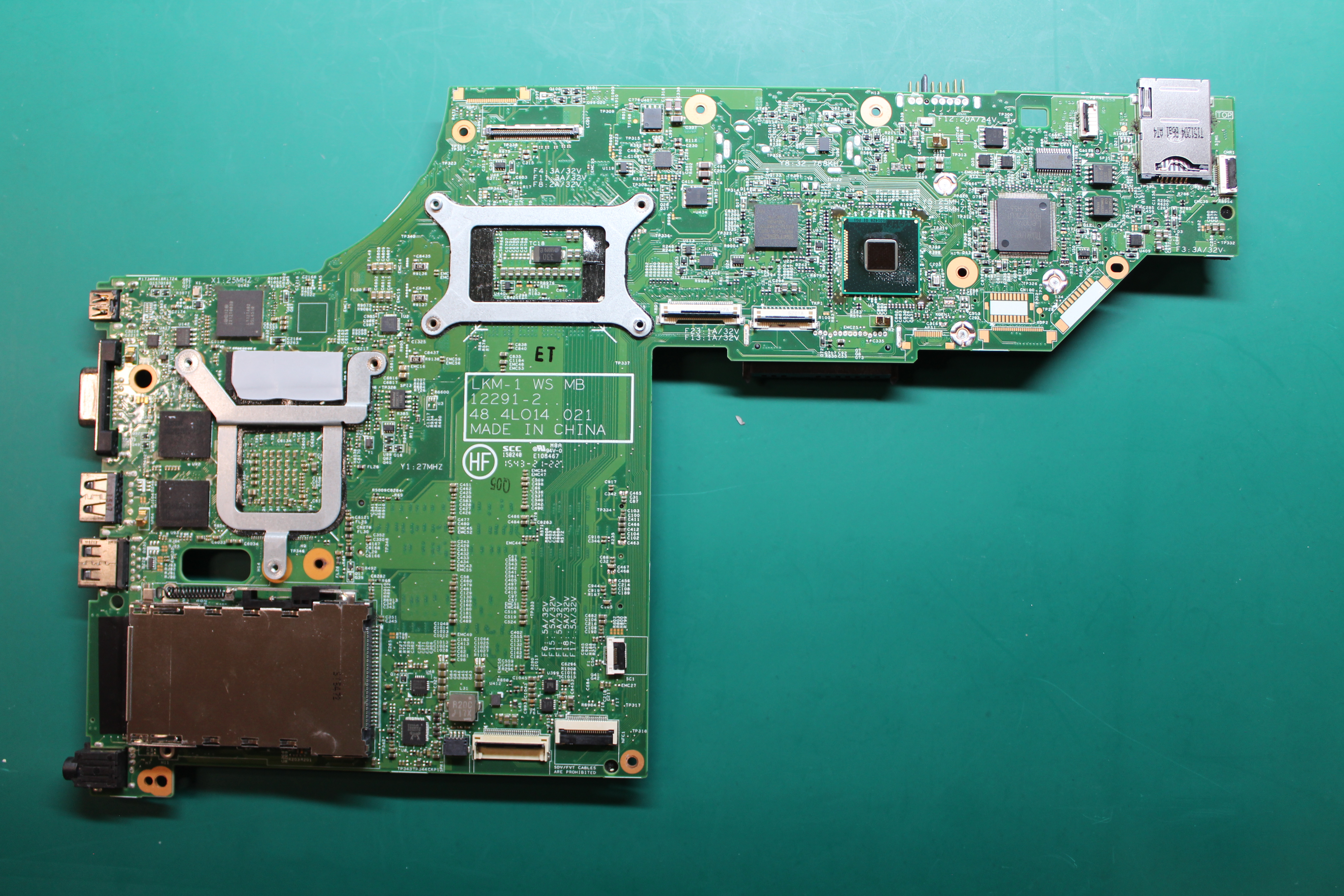
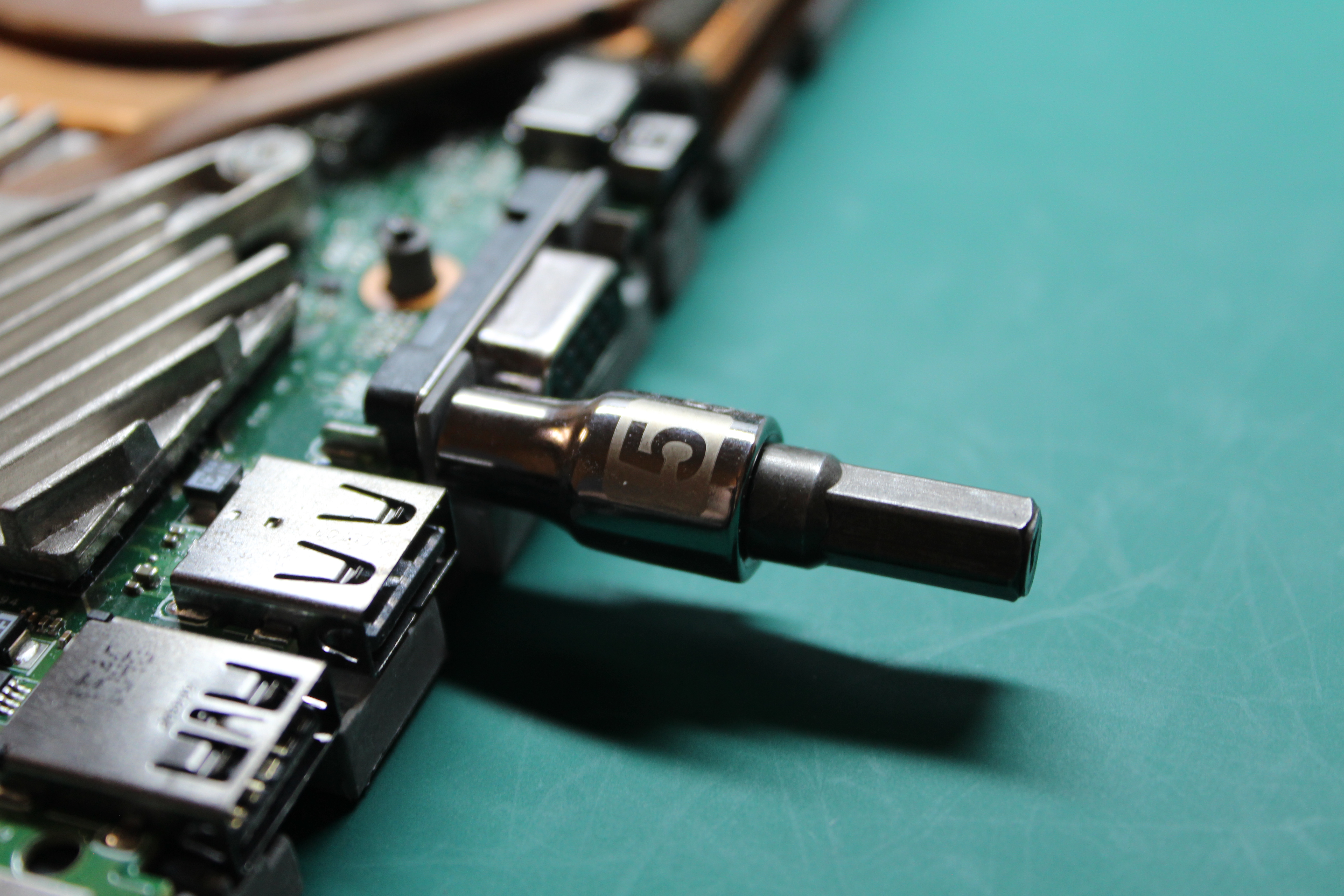
You will have to disassemble all the way down to taking the motherboard out in order to get to the BIOS chips. If you’re initially uneasy about this, don’t worry, the only tool you need is a Phillip’s head screwdriver (#0), a 5mm hex head (for the VGA nuts), some organization, and patience.
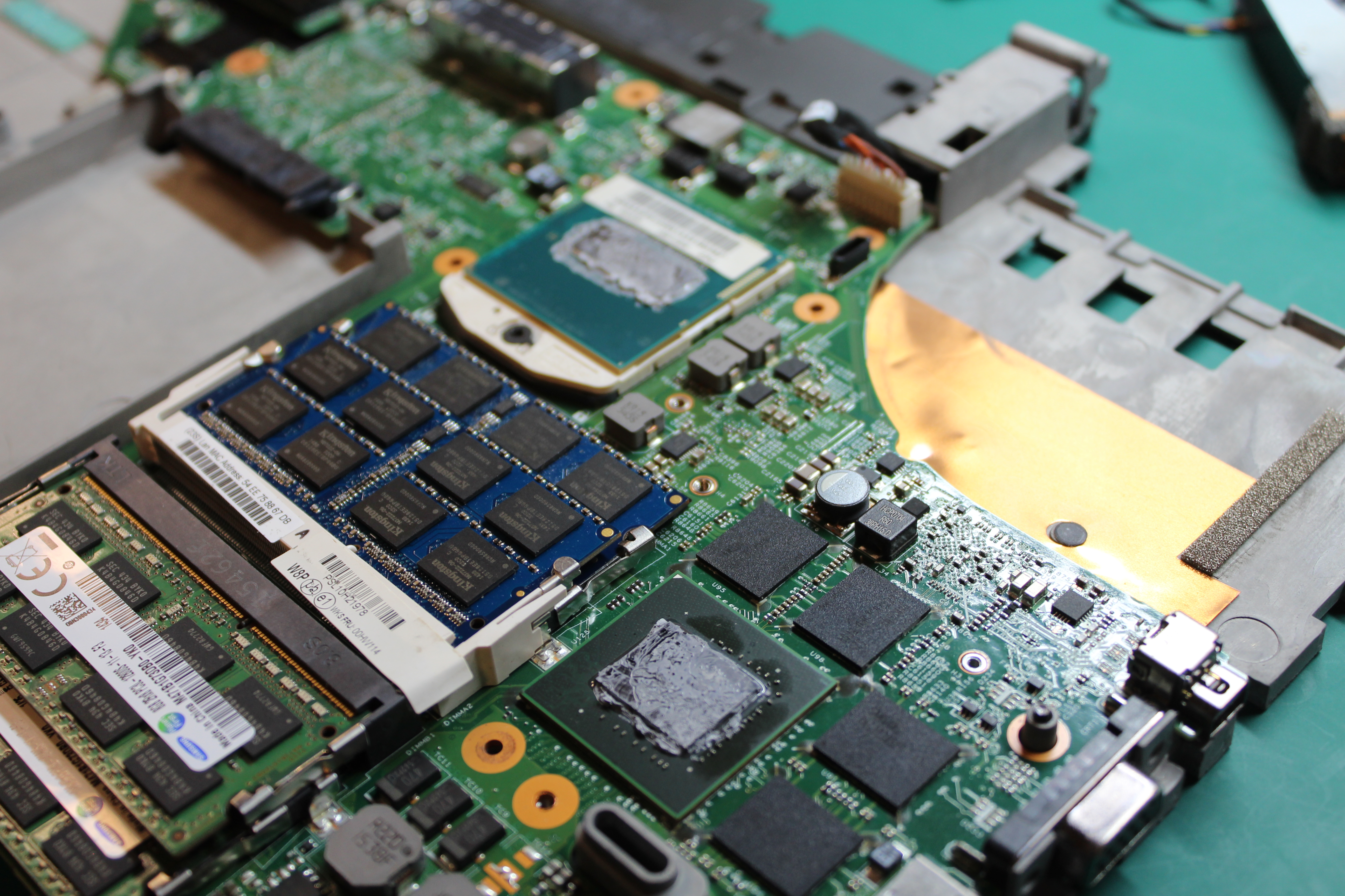
While you’re at it, you might as well clean the inside of the W541 and repaste the CPU. There are plenty of guides (and opinions) on how to apply thermal paste out there.
Connecting the flasher
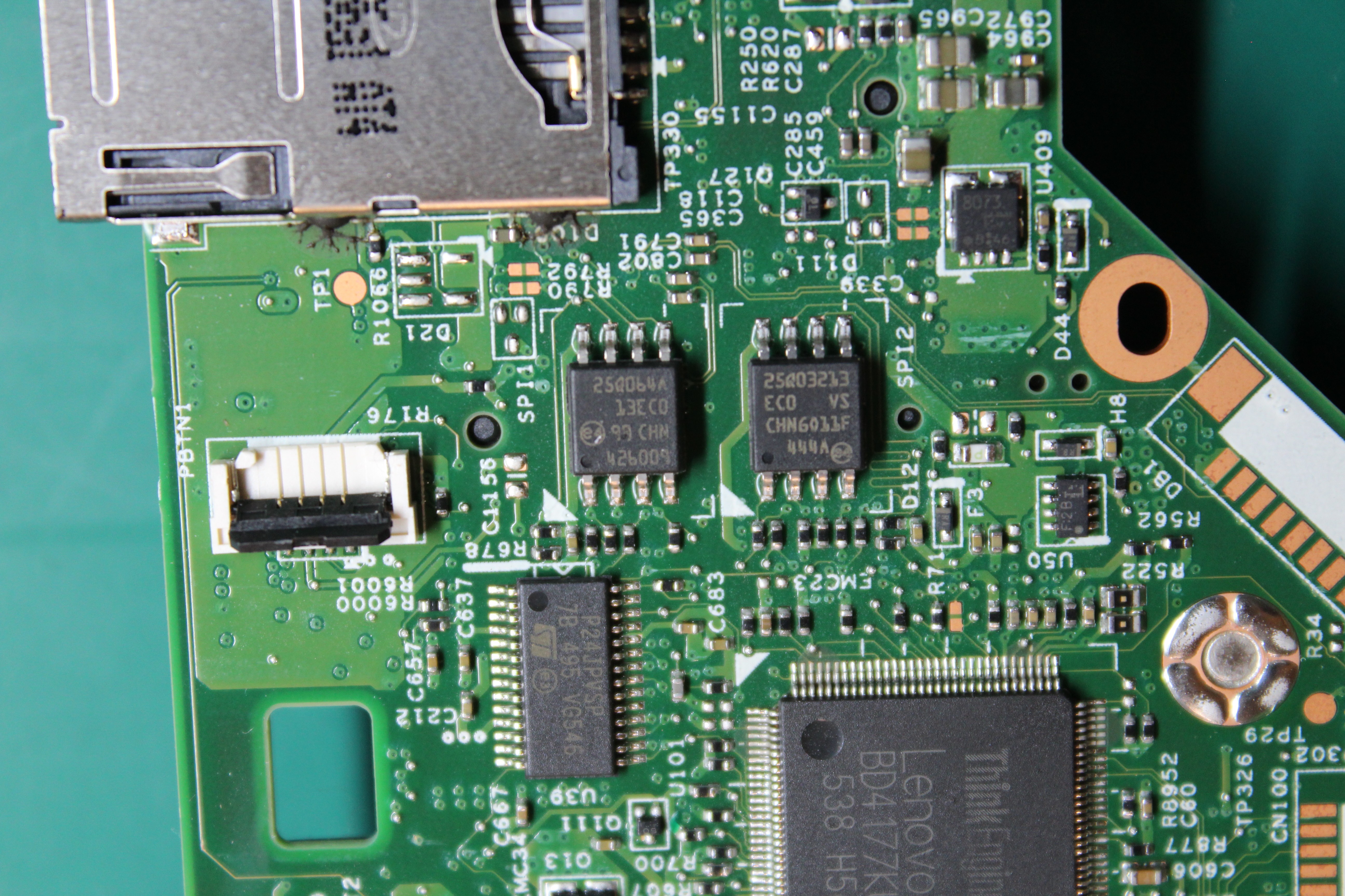
Take a high-resolution, detailed photo of each chip and make sure you can read the text on them before putting on the clip. You may need to know the exact name of the chip once in the later steps. However, the only chips I’ve seen documented for the W541 are the Micron N25Q032A and N25Q064A, and that’s what mine had as well.
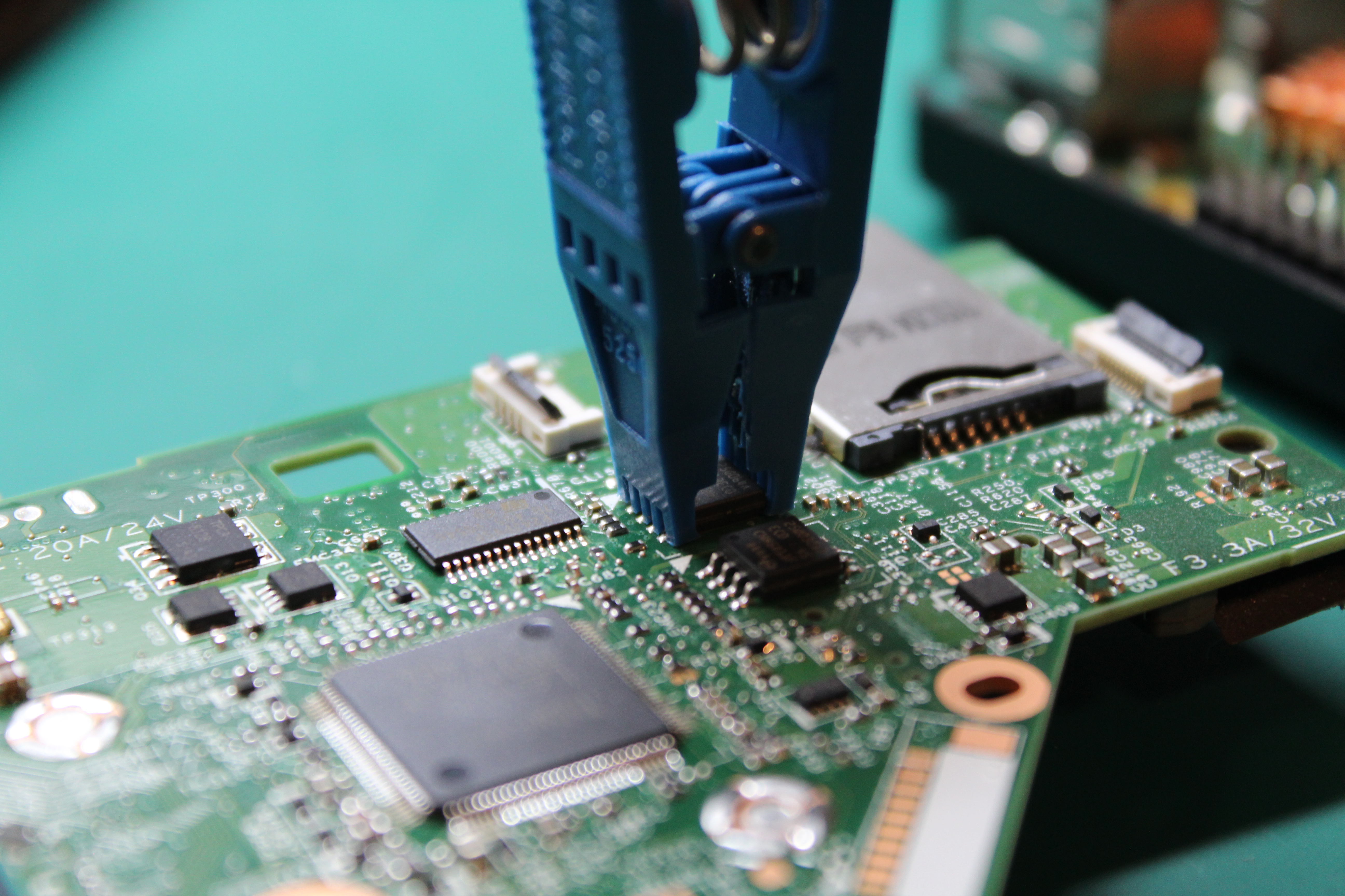
Align pin 1 (CS) of the clip with the dot on the chip, and attach it to the top chip. In my case, I couldn’t get a good read of the chip, even after cleaning pins with isopropyl alcohol, tidying up the clip itself to remove any excess plastic, and reconnecting plenty of times. It turns out, the power supplied by the Pi wasn’t sufficient to power the BIOS chip. If this happens to you, read the next paragraph very carefully.
If you can’t get a good read of either BIOS chip using a Raspberry Pi, you can either purchase an external programmer (the CH341A or the new CH341A V1.7) to perform the flashing. there are plenty of guides online showing how to use them. However, I found a method that works as well without having to purchase anything else, or use an external power supply. Boot into the W541’s default Lenovo BIOS and make sure the “Wake On LAN” config is set to “AC Only”, then connect your charger and a network cable connected to a router or switch to the motherboard (you may need to reattach the CPU heatsink). You will disconnect the VCC wire from the clip, and leave everything else plugged in. What’s happening here is the W541 itself is providing the power to the BIOS chip, and all you have to do is read it. This could be risky if you accidentally short something while there is power going to the motherboard, so be careful, but it worked for me.
I had to interrupt my original attempt at flashing due to not being able to read the chip. Knowing that I would have to get to the BIOS yet again, I didn’t want to disassemble everything a second time. So I took a Dremel to the chasis in order to give me access to where the BIOS chips are. As you can see, they’re located right underneath the keyboard.
Reading
Once the clip is connected, power on the Raspberry Pi and SSH into it (mine has the hostname flasher because that’s all I use it for).
ssh flasher
Make a directory just for the W541:
mkdir w541
cd w541
It’s a good idea to make an alias so that you don’t have to type as much, and also to add the alias to your ~/.bashrc as well.
echo "alias fr='sudo flashrom -p linux_spi:dev=/dev/spidev0.0,spispeed=512" >> ~/.bashrc && source ~/.bashrc
Now run it and view its output:
fr
If you see the following message:
No EEPROM/flash device found.
Shut down the Raspberry Pi (sudo init 0), disconnect the power, re-attach the clip, and try again. It may take a few tries, and that’s okay. However, if it still doesn’t read the chip after you’re positive you have a good connection, see my method in the Connecting the Flasher section, as this is exactly what happened to me.
You should see one of the following messages, depending on which chip you’re connected to:
Using clock_gettime for delay loops (clk_id: 1, resolution: 1ns).
Found Micron/Numonyx/ST flash chip "N25Q064..3E" (8192 kB, SPI) on linux_spi.
This is the 8MB (bottom) chip.
Or:
Using clock_gettime for delay loops (clk_id: 1, resolution: 1ns).
Found Micron/Numonyx/ST flash chip "N25Q032..3E" (4096 kB, SPI) on linux_spi.
This is the 4MB (top) chip.
It doesn’t matter which order you go, just be consistent with how you label or name the files. We’ll start with the 4MB top chip first in this guide, so set your CHIP environment variable accordingly:
CHIP="N25Q032..3E"
Now you can get your first read:
fr -c "$CHIP" -r top_01.bin
It will take a minute to finish, then run it again with a new file name:
fr -c "$CHIP" -r top_02.bin
You’ll want to change ownership of the files to your standard user (since flashrom is ran by root via sudo):
sudo chown $USER:$USER *.bin
Then check if there’s any difference between them:
diff top_01.bin top_02.bin
If there’s any output (there should be none), power down the Pi, re-attach the clip, and basically start over. If that keeps happening, you could lower the spispeed in your alias to something like 128, and that will just make everything take longer. However, there’s probably no difference between the files, so you can now move on to powering down the Pi, unplug it’s power, de-attach the clip and then attach it to the bottom BIOS chip.
With the clip attached to the bottom BIOS chip, plug in the Pi’s power, wait for it to boot up, then SSH into it again.
ssh flasher
Go into the directory you created for the W541 and run fr again:
cd w541
fr
You should get the output of the other chip, and you’ll need to set the new CHIP environment variable:
CHIP="N25Q064..3E"
Once again, you’ll read this chip twice and compare the difference:
fr -c "$CHIP" -r bottom_01.bin
fr -c "$CHIP" -r bottom_02.bin
sudo chown $USER:$USER *.bin
diff bottom_01.bin bottom_02.bin
Again, you shouldn’t see any output from the last command, and you can proceed with combining the ROM:
cat bottom_01.bin top_01.bin > original_12m.bin
Now we need to get the files to a more powerful computer to compile coreboot with it. Make a directory on the machine that will compile coreboot, and scp over the files:
mkdir -p ~/Documents/roms/w541
cd ~/Documents/roms/w541
scp tomo@flasher:/home/tomo/w541/*.bin .
This should get you all the .bin files (we’ll need them all, just in case) on a machine that we’ll now want to install coreboot as a build process.
Building
On this more powerful machine, clone coreboot and its submodules:
git clone https://review.coreboot.org/coreboot ~/workspace/coreboot
cd ~/workspace/coreboot
git submodule update --init --recursive --remote
git fetch --all --tags --prune
cd 3rdparty/blobs
git fetch --all --tags --prune
The first thing you’ll want to do is build a tool called ifdtool:
cd ~/workspace/coreboot/util/ifdtool
make && sudo make install
You can then run this tool on your ROM to extract out the separate “pieces” of the chip:
cd ~/Documents/roms/w541
ifdtool -x original_12m.bin
However, if you get the following error:
Warning: No platform specified. Output may be incomplete
File original_12m.bin is 12582912 bytes
You can simply run it on the bottom (8MB) ROM:
ifdtool -x bottom_01.bin
This should get you an output similar to the one below, which is good enough for us to work with:
Warning: No platform specified. Output may be incomplete
File bottom_01.bin is 8388608 bytes
  Flash Region 0 (Flash Descriptor): 00000000 - 00000fff
  Flash Region 1 (BIOS): 00500000 - 00bfffff
Error while writing: Success
  Flash Region 2 (Intel ME): 00003000 - 004fffff
  Flash Region 3 (GbE): 00001000 - 00002fff
  Flash Region 4 (Platform Data): 00fff000 - 00000fff (unused)
We just rename the files:
mv flashregion_0_flashdescriptor.bin descriptor.bin
mv flashregion_2_intel_me.bin me.bin
mv flashregion_3_gbe.bin gbe.bin
And we can get back to work in the coreboot directory:
cd ~/workspace/coreboot
First, clean the environment:
make distclean
Now we need to get the mrc.bin file, which is simply following the instructions here:
make -C util/cbfstool
cd util/chromeos
./crosfirmware.sh peppy
../cbfstool/cbfstool coreboot-*.bin extract -f mrc.bin -n mrc.bin -r RO_SECTION
Copy the mrc.bin file to be with the rest of the files for the W541:
cp mrc.bin ~/Documents/roms/w541
Now we should have all the files needed to configure coreboot. Enter the menuconfig for coreboot:
cd ~/workspace/coreboot
make menuconfig
This will enter you into a menu much like when you compile a Linux kernel, where you can select the options.
Here are the selections I chose, many are already selected by default, and you should also take note of what may be selected by default that is not selected below (don’t worry if you see some options that end with (NEW)):
General Setup
    - Option backend to use (Use CMOS for configuration values)  --->
    - [*] Include the coreboot .config file into the ROM image
    - [*] Create a table of timestamps collected during boot
    - [*] Allow use of binary-only repository

Motherboard
    - Mainboard vendor (Lenovo)
    - Mainboard model (ThinkPad W541)
    (The other options should update automatically once the above are selected)

Chipset
    - [*] Enable VMX for virtualization
    - [*] Set IA32_FEATURE_CONTROL lock bit
    - [*] Lock the AES-NI enablement state
    - [*] Add a System Agent binary
      (/home/tomo/Documents/roms/w541/mrc.bin) Intel System Agent path and filename
    - [*] Hide PEG devices from MRC to work around hardcoded MRC behavior
    - [*] Route all ports to XHCI controller in finalize step
    - [*] Disable Intel ME PCI interface (MEI1)
    - [*] Beep on fatal error
    - [*] Flash LEDs on fatal error
    - [*] Support bluetooth on wifi cards
    - [*] Add Intel descriptor.bin file
      (/home/tomo/Documents/roms/w541/descriptor.bin) Path and filename of the descriptor.bin file
    - [*]   Add Intel ME/TXE firmware
      (/home/tomo/Documents/roms/w541/me.bin) Path to management engine firmware
    - [*] Strip down the Intel ME/TXE firmware
      *** Please test coreboot with the original, unmodified ME firmware before using me_cleaner ***
    - [*] Add gigabit ethernet configuration
      (/home/tomo/Documents/roms/w541/gbe.bin) Path to gigabit ethernet configuration

Devices
    - Graphics initialization (Use libgfxinit)  --->
    - Early (romstage) graphics initialization (None)  --->
    - [*] Use onboard VGA as primary video device
    - [*] Allow coreboot to set optional PCI bus master bits
    - -*-   PCI bridges
    - [*]   Any devices
    - -*- Enable PCIe Common Clock
    - -*- Enable PCIe ASPM
    - [*] Enable PCIe Clock Power Management
    - [*] Enable PCIe ASPM L1 SubState
    - [*] Add a Video BIOS Table (VBT) binary to CBFS
      (src/mainboard/$(MAINBOARDDIR)/variants/$(VARIANT_DIR)/data.vbt) VBT binary path and filename

Generic Drivers
    - [*] PS/2 keyboard init
    - [*] Use legacy-BIOS alt-century byte in CMOS
    - [*] Support Intel PCI-e WiFi adapters

Security
    (Nothing selected)

Console
    - [*] Enable early (bootblock) console output.
    - [*] Enable console output during postcar.
    - [*] Squelch AP CPUs from early console.
    - [*] Send console output to a CBMEM buffer
      (0x20000) Room allocated for console output in CBMEM
    - [*] Use loglevel prefix to indicate line loglevel
    - [*] Use ANSI escape sequences for console highlighting
    - [*]   Show POST codes on the debug console

System Tables
    (Everything should be set correctly by default)
    - [*] Generate SMBIOS tables

Payload
    - Payload to add (SeaBIOS)  --->
    - SeaBIOS version (1.16.1)  --->
    - (3000) PS/2 keyboard controller initialization timeout (milliseconds)
    - [*] Hardware init during option ROM execution
    - [*]   Hardware Interrupts
    - [*]   Include generated option rom that implements legacy VGA BIOS compatibility
    - (0)   SeaBIOS debug level (verbosity)
    - [*]   Use LZMA compression for secondary payloads
    (I usually don't select any secondary payloads, but you can add them to your config if you need.)

Debugging
    (Nothing selected)
Save your config to the ~/workspace/coreboot directory so that coreboot will use it when building, and Exit.
Now for the home stretch, we have a lot of compiling to do. First compile the cross-compiler and build tools:
make crossgcc-i386 CPUS=$(nproc)
make iasl CPUS=$(nproc)
The first command will take a while, depending on the speed of the machine running it. The second command is quick. Now we compile the coreboot ROM for the W541:
make CPUS=$(nproc)
A lot of output should go across the screen, but you’re looking for this to be the last line of output:
Built lenovo/haswell (ThinkPad W541)
If everything is successful, you’ll have a coreboot.rom image in the build/ directory. Move it back to your machine-specific directory:
mv build/coreboot.rom ~/Documents/roms/w541
And go ahead and work from that directory:
cd ~/Documents/roms/w541
Now we just need to split the ROM for each chip:
dd if=coreboot.rom of=coreboot_top.rom bs=1M skip=8
dd if=coreboot.rom of=coreboot_bottom.rom bs=1M count=8
Finally, send the images over to the Pi:
scp coreboot_*.rom tomo@flasher:/home/tomo/w541
Writing
On the Pi, you should have received the coreboot images in the ~/w541 directory, so ssh into it and work from there:
ssh flasher
cd w541
Your clip should still be connected to the bottom BIOS chip of the W541’s mainboard. Let’s get one more read out of it and make sure it matches to ensure we still have a good connection, then check the diff:
fr -c "$CHIP" -r bottom_03.bin
sudo chown $USER:$USER *.bin
diff bottom_03.bin bottom_02.bin
Again, there shouldn’t be any output, and if so, power down the Pi, disconnect the clip, reattach it, and try connecting it again. Now we write the bottom image to the chip:
fr -c "$CHIP" -w coreboot_bottom.rom
It should read, write, and validate all successfully. When it completes, power down the Pi, disconnect its power, then place the clip on the top BIOS chip, and ssh back into it:
ssh flasher
cd w541
Now let’s get one more read out of the top chip, first by setting the $CHIP environment variable, and check the diff:
CHIP="N25Q064..3E"
fr -c "$CHIP" -r top_03.bin
sudo chown $USER:$USER *.bin
diff top_03.bin top_02.bin
And if there’s no output from the diff, write the coreboot top image:
fr -c "$CHIP" -w coreboot_top.rom
This one will take a little longer, since the image is twice the size of the bottom, but when it finishes, shut down the Pi, disconnect its power, remove the clip, and you can begin reassembling the W541.
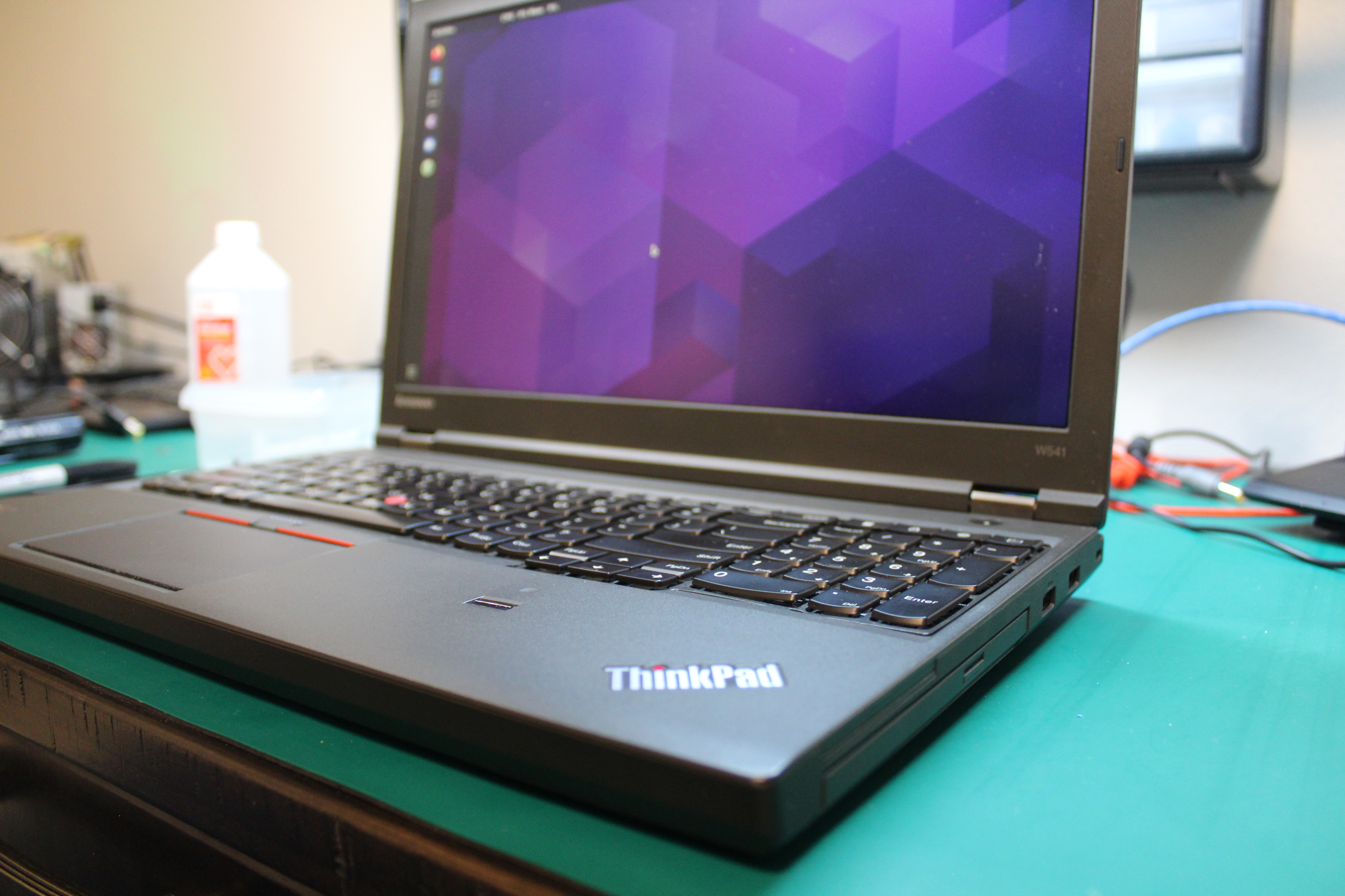
You might want to get clever about only connecting what you need to see the screen. As long as you can see the SeaBOIS screen when the W541 boots, then flashing was successful and you can complete the reassembly. Personally, I never bother to add a splash image. Also note that the first boot after flashing coreboot will take significantly longer than normal. I was sitting at a blank screen for roughly 20 seconds before the SeaBIOS came up the first time, which of course feels like an eternity.
Keep the original BIOS image backed up somewhere safe. Not that you’d want to go back to using it, but it may be helpful for yourself or others in the future.
Enabling the dGPU
Right off the bat, you only have the integrated Intel GPU (iGPU), and it’s likely that the ability to use an external display is limited in this mode. To enable the more powerful Nvidia discrete GPU (dGPU), you’ll need to modify a line in your /etc/default/grub config file. Find the line that starts with GRUB_CMDLINE_LINUX_DEFAULT and make it look like this:
GRUB_CMDLINE_LINUX_DEFAULT="iomem=relaxed quiet"
Save the file and reboot. You also now get the benefit of being able to update your BIOS via internal flashing with this setting, rather than having to disassemble your W541 all over again. This will be useful as there is a libre mrc.bin replacement in development, and the developers need people to test.
After rebooting, clone the coreboot repo on the W541, enter the nvramtool directory, and make it:
mkdir ~/workspace
git clone https://review.coreboot.org/coreboot ~/workspace/coreboot
cd ~/workspace/coreboot/util/nvramtool
make
This will create a binary in that directory, that you can run to verify its current settings:
sudo ./nvramtool -a
boot_option = Fallback
reboot_counter = 0x0
debug_level = Debug
nmi = Enable
power_on_after_fail = Disable
first_battery = Primary
wlan = Enable
trackpoint = Enable
fn_ctrl_swap = Disable
sticky_fn = Disable
usb_always_on = Disable
backlight = Keyboard
f1_to_f12_as_primary = Enable
enable_dual_graphics = Disable
volume = 0x3
The config enable_dual_graphics needs to be enabled, so run:
sudo ./nvramtool -w enable_dual_graphics=Enable
Then you can run sudo ./nvramtool -a again to verify, but you must reboot in order for the changes to actually take effect.
Once rebooted, run the following command and you should see your dGPU is enabled:
lspci | grep VGA
00:02.0 VGA compatible controller: Intel Corporation 4th Gen Core Processor Integrated Graphics Controller (rev 06)
01:00.0 VGA compatible controller: NVIDIA Corporation GK106GLM [Quadro K2100M] (rev a1)
Conclusion
What a task! The W541 will probably be the newest ThinkPad to support coreboot, sadly, since all machines after it have Intel Boot Guard enabled, preventing the possibility of freeing the machines.
Please spread the word about coreboot, as more awareness about it (and the dangers of proprietary BIOSs) increases overall freedom for users.